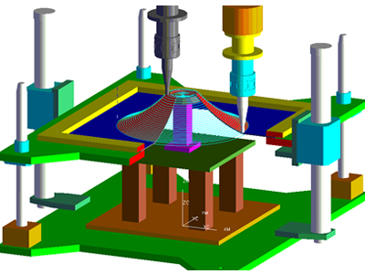
Internationally-acknowledged Company with Leading Technology Development

FINEDNC’s development ability has been recognized both in South Korea and overseas. We always continuously apply ourselves to every mission with the challenging spirit to go further and provide more advanced technology.

1. 3D PRINTER EQUIPMENT INTRODUCTION

3d_printer_intro_img_01

INFORMATION

  • Model Pro-X 800 (Stereolithography technology)
  • Manufacturer 3D SYSTEMS (U.S.A)
  • Place of Installation FINEDNC Anyang Factory Advanced Development Team
  • Installation Date 2016.09.20
  • Max Part Weight MAX 75kg
  • Accuracy 0.025-0.05 mm per 25.4 mm of part dimension
  • Max Build Volume(Full) 650 X 750 X 550mm(if the final product exceeds the dimension, it could be printed partially then assemble as a whole product.)
  • Materials of Equipment Plastic category
  • Printing Materials Accura 25 (PP substitute, ivory color) Accura ClearVue (PC substitute, transparent color)
  • Process Method SLA(Stereolithography) method (using a coagulated ultraviolet laser, curing the photocurable liquid reson contained in the water tank to produce parts in layers)
 

2. 3D PRINTER DRIVING METHOD

3d_printer_intro_img_02

1

3d_printer_intro_img_03

2

3d_printer_intro_img_04

3

3d_printer_intro_img_05

4

<Product Printing Principle>
1. Curing the liquid resin appllied on the top of the platform to a single layer shape of the product using laser.
2. Redepositing the 1st. Step after moving the platform downward 0.1mm.
※ Through the repetitive work of the above steps, print from the bottome layer to the final form layer by layer.

3. 3D PRINTER FEATURES

Advantages

  • Automatic support creation (no support material required)
  • Simplified the manufacturing process
  • Significantly shorten production cost and period
  • Meet requirement of precise and robust
  • Low material waste
  • No need to produce processing JIG

Application Fields

3d_printer_intro_img_06

4. 3D PRINTER INTRODUCTION VIDEO

5. 3D SCANNER INTRODUCTION

scanner_intro_img_03

INFORMATION

  • Equipment SMART SCAN(High Density Point Cloud Generated)
  • Place of Installation FINEDNC Anyang Factory Advanced Development Team
  • Installation Date 2016.09.19
  • Using Method – Do reversal design of the product by scanning it on the turntable – Measuring the product
 

Scan Range & Resolution, Precision

  • Field of View M-125 M-300 M-600 M-850
  • Measuring RANGE X*Y(mm) 105*90 240*300 500*380 650*560
  • Measuring Length Z(mm) 60 150 300 400
  • X*Y Resolution(㎛) 45 100 205 265
  • Accuracy(㎛) ±10 ±26 ±51 ±72

6. 3D SCANNER EQUIPMENT FEATURES

scanner_intro_img_02

Fast & Accurate

  Rapid scanning regardless target object’s size and shape. High resolution sensor and advanced interface for accurate data acquisition.
 

Diversified Application Fields

  Providing high performance and accuracy, various measurement areas. Available to be used in various fields including product development and quality inspection.
 

Various Measurement Areas

  In addition to a wide range of measurement from 60mm to 1550mm, the smartSCAN and stereoSCAN can additionally scan for very small or large areas (25mm / 2500mm). Even though the object has asymmetric polygons(10°, 20°, 30°), two cameras of the scanner could still measure the accurate information under the hard-to-measure areas.
 

Automation Solutions

  It is easy to use by general users as well as professional workers, and can be automatically measured in conjunction with additional devices such as robots or turntables for site automation.
 

7. 3D SCANNER WORKING EXAMPLE VIDEO

Forming Machine

Principle of processing • Master JIG created by our new Technology sets below flat tool fixed by Blank Holder • Increasing of Blank Holder fixing material • Rotating of Forming Tool With Master JIG as center
Forming? By repetitive Blank Holder increasing and rotating of Forming Tool, Material is under the Pressure then Forming form will appear
equipment_s_12_01

 Picture of processed object

SPEC   FORMING MACHINE
Process system Stroke
X Y Z spindle Process system 2000 × 1000 x 500 / Available Product weigh 400kg

 Photo/Equipment Name

equipment_b_12_01

entire equipment image

equipment_b_12_02

NC Forming M/C Control unit

equipment_b_12_03

Product Modeling

NCT(Numerical Control Turret), NC. TPP

Principle of processing With its computer numerical control, the equipment uses the tool installed in the turret in order for PUNCH PRESS. Therefore, it makes possible computer-based auto control.
What is NCT? NCT(Numerical Control Turret), NC. TPP NC that stands for numerical control is an automatic machine to process automatically after P/G input, such as CNC or MCT. TPP that stands for Turret Punch Press is a disk (top) based press with numerical control.
equipment_s_01_01

 Picture of processed object

SPEC    NCT (FINN POWER – FS EXPRESS)
Driving Type X, Y, and Z Axes Processing Type
stroke 1600 × 800

 Photo/Equipment Name

equipment_b_01_01
equipment_b_01_02

Manual Bending Machine

Principle of processing Fixed in the frames moving up and down, the machine transforms steel plates by imposing an even load.
What is bending machine? It is a machine that impose pressure on a metal plate in the upper and lower frames with the use of Bending Punch and Die and bends the material to produce a product. By replacing a shape frame, it is possible to bend a material in various angles and shapes and is divided into manual and automatic types.
equipment_s_02_01

 Picture of processed object

SPEC   AMADA RG-50 AMADA RG-80
Driving Type Hydraulic Pressure Hydraulic Pressure
Max Load 3000KG 3000KG

 Photo/Equipment Name

equipment_b_02_01

Manual Bending Machine (AMADA RG-50)

equipment_b_02_02

Manual Bending Machine (AMADA RG-80)

TIG, Spot Welding Machine

Principle of processing Welding process is a technique to heat and melt a metal material on connection part in order to rearrange atomic combination of different two materials for bonding.
What is welding? Inert gases, such as Argon, Ar, and He, are used as shield gas and melt a material with arc heat generated in non-consumable tungsten electrodes and the material. SPOT Welding is a sort of welding technique. In the welding process, the material to weld is put in between electrode tips. When it is pressed and become electrically current, Joule heating generated in the way heats and melts a connection part.

 Picture of processed object

SPEC   PTN301AD / PTN302AD CTV-220
Rated Output 10-220(ARC 180) AC 220/380/440±10%
Rated Frequency 50/60 HZ 50/60Hz±2Hz

 Photo/Equipment Name

equipment_b_03_01

TIG Welding Machine (Welding Partner PTN301AD, PTN302AD)

equipment_b_03_02

Spot Welding Machine (Chowel CTV-220)

PEM PRESS

Principle of processing Based on Z axis, the machine moves. And with the use of its hydraulic pressure, the equipment imposes an intensive load on a particular part.
What is PEM PRESS? The equipment is used to press-fit clinching, S/O bolt & nut, and various kinds of PEM, STUD, and PIN.

 Picture of processed object

SPEC   PEM PRESS 615 PEM PRESS 630
Driving Type Z Axis Hydraulic Pressure Driving Type Z Axis Hydraulic Pressure Driving Type
Arm Depth 615mm 630mm
Max Load 3000KG 3000KG

 Photo/Equipment Name

equipment_b_04_01

PEM PRESS 615 (Jangsung Industrial Machinery)

equipment_b_04_02

PEM PRESS 630 (Jangsung Industrial Machinery)

LASER cutting machine

Principle of processing By focusing laser beam on the minimum diameter, the machine heats and vaporizes a material for cutting.
What is laser cutting? It is a cutting method with the use of laser beam energy. Usually, CO2 and nitrogen are used for laser which had a narrower cutting width and better precision cutting than Oxygen-Acetylene flame.
equipment_s_05_01

 Picture of processed object

SPEC   FIN POWER – D0MINO MAZAK – OPTIPLEX NEXUS3015
Driving Type X, Y, and Z Axes 2D/3D X, Y, and Z Axes 2D Processing Type
stroke X: 3050 Y: 1540 Z: 400 (mm) X: 3050 Y: 1525 (mm)
Max Load 3000KG 3000KG

 Photo/Equipment Name

equipment_b_05_01

FIN POWER – D0MINO

equipment_b_05_02

MAZAK – OPTIPLEX NEXUS3015

Semi-automatic Bending Machine (FINN POWER – BCE5-3)

Principle of processing Based on its computer based numerical control, the machine uses its tool for press. Therefore, it makes possible computer-based automatic control.
What is semi-automatic benching machine? It is a model developed in the way of changing conventional manual bending machine into semi-automatic structure machine. Semi-automatic running means that only the process of loading a processed product is performed manually. Though manual loading, user-friendly design makes it easy to work.

 Picture of processed object

SPEC   X, Y, and Z Axes 2D Processing Type (FINN POWER – BCE5-3)
Driving Type X, Y, and Z Axes Processing Type
stroke 1600 × 800

 Photo/Equipment Name

equipment_b_06_01
equipment_b_06_02

Hydraulic Press (Youngjin Hydraulic Pressure – 400TON)

Principle of processing The machine changes a plate in an intentional shape or dimensions by bending or putting in a frame at room temperature.
What is hydraulic press? Based on Pascal’s law according to which pressure works constantly in any place of closed space, the output power is used to compress, cut, and bend such objects to process as metallic and non-metallic materials with the use of die. With the equipment, users are able to process a material in a proper shape.

 Picture of processed object

SPEC   Semi-automatic Bending Machine (FINN POWER – BCE5-3)
Driving Type Hydraulic Pressure
Load 4000KG

 Photo/Equipment Name

equipment_b_07_01
equipment_b_07_02

MCT-1

TRAVELS S.A.E METRIC
X Axis 30″ 762 mm
Y Axis 16″ 406 mm
Z Axis 20″ 508 mm
Spindle Nose Table (~max) 24″ 610 mm
Spindle Nose Table (~min) 4″ 102 mm
TABLE S.A.E METRIC
Length 36″ 904 mm
Width 14″ 356 mm
T-Slot Width 5/8″ 16 mm
T-Slot Center Distance 4.92″ 125.0 mm
Number of Std T-Slots 3 3 mm
Max Weight on Table (evenly distributed) 3000 lb 1361 kg
SPINDLE S.A.E METRIC
Max Rating 30 hp 22.4 kw
Max Speed 8100 rpm 8100 rpm
Max Torque 90 ft-lb@2000rpm 1220 Nm@2000 rpm
Drive System Inline Direct-Drive Inline Direct-Drive
Max Torque w/opt GeARBOX 205 ft-lb@450rpm 339 Nm@450 rpm
Taper  CT or BT 40 CT or BT 40
Bearing Lubrication  Air/Oil Injection Air/Oil Injection
Cooling Liquid Cooled Liquid Cooled
FEEDRATES S.A.E METRIC
Rapids on X 1000 in/min 25.4 m/min
Rapids on Y 1000 in/min 25.4 m/min
Rapids on Z 1000 in/min 25.4 m/min
Max Cutting 650 in/min 16.5 m/min
AXIS MOTORS S.A.E METRIC
Max Thrust X 2550 lb 11343 N
Max Thrust Y 2550 lb 11343 N
Max Thrust Z 4200 lb 18683 N
TOOL CHANGER S.A.E METRIC
Type Carousel (SMTC Optional) Carousel (SMTC Optional)
Capscity 20 20
Max Tool Diameter (full) 3.5″ 89 mm
 Max Tool Weight 12 lb 5.4 kg
Tool-to-Tool (avg) 4.2 sec 4.2 sec
Chip-to-Chip (avg) 4.5 sec 4.5 sec
GENERAL S.A.E METRIC
Air Required 4 scfm. 100 psi 113 L/min, 6.9 bar
Coolant Capacity 55 gal 208 L

 Photo/Equipment Name

equipment_b_08_01

PEM PRESS

Principle of processing Based on Z axis, the machine moves. And with the use of its hydraulic pressure, the equipment imposes an intensive load on a particular part.
What is PEM PRESS? The equipment is used to press-fit clinching, S/O bolt & nut, and various kinds of PEM, STUD, and PIN.

 Picture of processed object

SPEC   PEM PRESS 615 PEM PRESS 630
Driving Type Z Axis Hydraulic Pressure Driving Type Z Axis Hydraulic Pressure Driving Type
Arm Depth 615mm 630mm
Max Load 3000KG 3000KG

 Photo/Equipment Name

equipment_b_09_01

PEM PRESS 615(Jangsung Industrial Machinery)

equipment_b_09_02

PEM PRESS 630(Jangsung Industrial Machinery)

MCT(machining center)

Principle of processing After G code is written with the computer program CAM, the tool installed in MCT is used for processing. The equipment makes possible computer-based automatic control.
What is MCT? It is a MCT(machining center) complex NC(numerical control) machine tool. Equipped with automatic switch device of tools or automatic selection function, the NC machine tool makes possible various kinds of processing and multi-surface processing, including milling cutting, drilling, and tapping.

 Picture of processed object

SPEC   MCT (machining center)
Driving Type X, Y, and Z Axes 2D/3D Processing Type
stroke 762 X 406 X 508

 Photo/Equipment Name

equipment_b_10_01
equipment_b_10_02

Cutting Plotter

Principle of processing Based on the 2D drawing of computer program, the holder blade installed in cutting plotter is used for processing. The equipment makes possible computer-based automatic control.
What is Cutting Plotter? It is a digital control servo motor machine to cut various kinds of flat sheets with the use of 2D program.

 Picture of processed object

SPEC   Cutting Plotter
Driving Type X and Y Axes 2D Processing Type
stroke 1740 X 920

 Photo/Equipment Name

equipment_b_11_01
equipment_b_11_02